


Each Bongo being almost one of a kind, due to the enormous number of pick 'n mix variations available, you may find that aspects of what is shown here do not match your vehicle. Ours is a "new shape" (Feb 1999 to August 2001 base models series), manufactured in December 2000, and first registered in April 2001. Full code info is VIN SG5W-403xxx; Grade RFV-S Special Edition; Model-Spec S55H-5BA. I assume that the last of those terms ("Model-Spec") is a record of exactly which "Special Edition" it is - i.e., which options were fitted.
In fact, a majority of the available options were fitted to this vehicle which, together with after-market add-ons (LPG conversion, full camper conversion, coolant alarm, TM-2, etc.) meant that there's a lot of additional cabling and hardware (e.g., the LPG ECU), particularly under the dash, and this made access very difficult for some elements of the cruise control installation. So, the better equipped the Bongo, the harder the installation is likely to be.
The LPG hardware in the engine compartment made it totally impossible to install the Waeco vacuum servo (actuator) there, without either interfering with other systems, or risking exceeding its max temperature limit - hence the location, and installation layout I've used. It might even be difficult for any V6, even if not LPG converted.
In any case, the method used here is equally applicable as an alternative approach for any Bongo, whether or not forced on you by space limitations.
1.) Vacuum servo (actuator) bolted on in the front compartment, using the engine air intake duct fixing bolt (lightweight servo, and wholly secure):
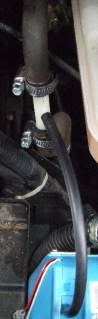
2.) Vacuum take off, directly in front of the brakes vacuum servo outlet:
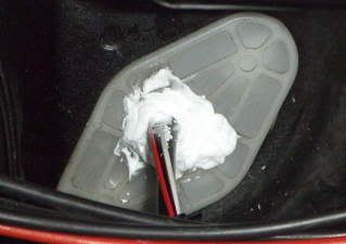
3.) Actuator bowden cable and wiring passed through the bulkhead into the cabin, using a large plastic blanking plate above the foot rest - where the clutch would be mounted in a manual bongo? WARNING - if you use this method, the plastic is too thick for the one grommet supplied by Waeco. I found that out too late, and have had to remove the grommet and bodge fill the large hole that left, with silicone sealant.:
4.) "Caburator (sic) shaft" ((page 6, D1 in manual), bent into a right angle ended bracket, supporting the clamped end of the bowden cable's outer sheath, and bolted to the steel upright behind and left of the interior fusebox. This is necessary for the bowden cable inner wire to reach the top of the accelerator pedal lever, as below.

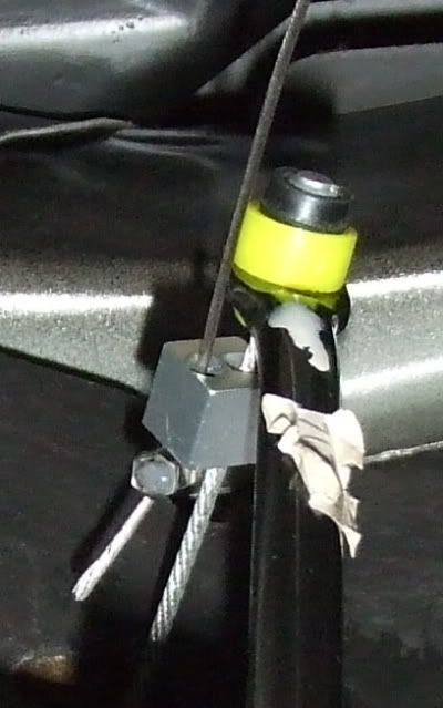
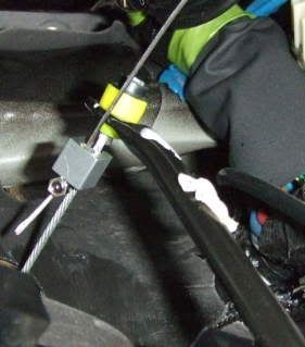
5.) Actuator bowden cable clamped to the engine throttle cable at the top of the accelerator pedal lever - page 7, E2 in the manual. The drawing there suggests that a fixed bracket is used for attachment but none is provided, and it is in fact essential to use the supplied cable clamp and cable stopper, as shown. When operated by the accelerator pedal, the engine throttle cable is pulled through the bulkhead lower left, but the actuator bowden cable, passing through the hole in the cable clamp, is not affected. When cruise control takes over, the cable stopper, clamped to the actuator cable, pulls up against the cable clamp, to operate the accelerator pedal lever and pull on the engine throttle cable. All stress is on the two small allen screws, one attaching the clamp to the throttle cable and the other clamping the stopper to the actuator cable, so those two screws must be fully tightened - and, I suggest periodically checked. In fact, I think I'll now Araldite lock mine. WARNING: If using this installation method, cover all trim and carpet openings around the accelerator pedal, before you drop clamp or stopper down into one of them - as I did!!
(EDIT, 28/09/09: I learned yesterday that DBO has lost his MS-50 cable stopper, from its location inside the engine bay, so the system therefore no longer works - and he has not yet found a replacement stopper. Bike ones, with wires clamped by washers, are I think not suitable. Anyone have a spare one, or know of a source?) EDIT: see separate posting below, on this subject.
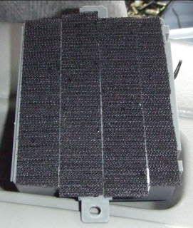
6.) Electronic module (p.8 in manual), with Velcro hook strips acroos its base:
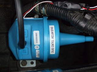
7.) Electronic module, Velcro-attached to carpet below below front heater unit - out of the way, out of the heater air flow, and totally secure (cabling since sleeved):
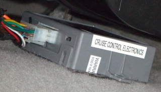
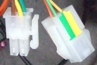
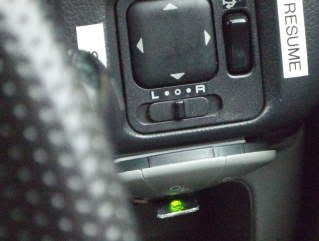
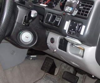
8.) Possibly temporary control unit location, horizontally inverted, just inside the driver's door. It's a very simple one hole, stuck on, installation, which works well, although I may look for a compatible steering column stalk. Anyone know if there's one which is plug-compatible, using the connectors shown? Meanwhile, I've fabricated a temporary LED-reflector, using baking foil attached to a bit of bracketry from my toolbox - will replace with a proper mirror, if made permanent:

9.) LED reflector from driver's viewpoint:
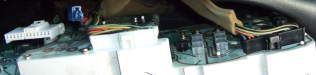
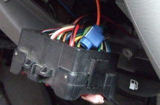
10.) Three (not two, as said elsewhere - in our case, at least) multi-plugs at rear of instrument panel. Access by removing four surround screws, unplugging cables from the surround to pull forward, then removing four instrument panel screws - hoping you don't have add-ons cabling in the way, making that very hard to do (as I found):
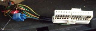
11.) Snap-Lok connected blue Waeco cable to blue/white cable output from middle connector - as B14 on page 8 of the manual. Apparently there's a terminal "SP+" at the rear of the instrument panel, from which you can also obtain the speedo output - but I found that out too late!:
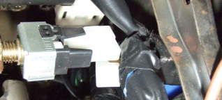
12.) Brake light switch, at rear of top of brake pedal. Access by removing the trim panel below the steering wheel (not the steering wheel shroud), unplug the connector (push on ribbed top clip, hard) and snap lock Waeco brown/white wire to the existing permanently 12v+ wire - confirm with a multimeter at the detached connector. Connect Waeco brown to the other wire by Snap-Lok.
13.) Securely attach the green earth wire to a multimeter-tested good chassis earthing point, rear of dashboard.
14.) Snap-Lok Waeco orange wire to the wire attached to the rear of Fuse 8, in the interior fusebox:
15.) My finished installation- electronic module under front heater, and control unit centre right.
With the loop wire cut (p.56, 2) and the sensitivity switch set to 'H' (P.56, 3), the system worked well first time out, and initial impressions are very good. Will write more on that, next week.
Sorry about the too small photos. Will try to find time to rectify that tomorrow (EDIT - now done), and will in any case, provide larger ones to Simon Jones, who is going to add some of this to his work in progress fact sheet.