


Pipe - expansion tank to heater circuit return
Moderators: Doone, westonwarrior
-
missfixit70

- Supreme Being
- Posts: 12431
- Joined: Fri Jun 01, 2007 3:53 pm
- Location: weymouth
Re: Pipe - expansion tank to heater circuit return
I think that one has been discussed to death, that the long life OAT red coolant has a higher BP  Do they add a further ingredient too? Make more sense writing OAT than BOOST to me.
You can't polish a turd - but you can roll it in glitter.
Re: Pipe - expansion tank to heater circuit return
Yer right Kirsty.  Unless someone has a theory on dragons blood having better coolant quality's i'll leave it there...
Wait just googled this... http://www.circletrack.com/enginetech/c ... index.html
Now i'm thinking... It maybe in reference to boost they use OAT the same way if you asked to borrow my Hoover, although i have a Miele i'd know what you mean... Or Dongle, for the generic flash drive like Kingston??

Wait just googled this... http://www.circletrack.com/enginetech/c ... index.html
Now i'm thinking... It maybe in reference to boost they use OAT the same way if you asked to borrow my Hoover, although i have a Miele i'd know what you mean... Or Dongle, for the generic flash drive like Kingston??
Cheaper by comparison to a race horse...

-
The Great Pretender

- Supreme Being
- Posts: 2671
- Joined: Thu Oct 19, 2006 10:10 pm
- Location: Wigan
Re: Pipe - expansion tank to heater circuit return
widdowson2008 wrote:Up 'till the stat opening, the pump shoves coolant basically through 3 different routes at the same time, and these are 1.header tank, 2.heater circuit, 3.bypass from head, and water will always favour the easiest route, ie biggest pipe as demonstrated in this pic.The Great Pretender wrote:Interesting, can you post your findings (as simply as possible for non tec peeps) of how you arrive at a maximum of 8% flow through the small pipe please.widdowson2008 wrote: Just done some calcs on pipe areas and the volume passing through cct 3 (from header tank) represents, at very best, 8% of circulating coolant. In the grand scheme of things, naff all.
The pipe diameters for the above 3 circuits are
1.header tank, 5.50 dia (area 24 sq mm)
2.heater, 13 dia (area 132.5 sq mm)
3.bypass 13 dia (area 132.5 sq mm)
Total area of all 3 circuits = 289 sq mm
Therefore, as a proportion, header tank flow to total area flow is 24 divided by 289 = 8% (ish)
Of course, once the stat opens, it presents a 4th path for the coolant to go down. this will reduce the 8% even further.
Does this make sense to you?
Didn't mean this to get too heavy a discussion - just intrigued by the purpose of the small pipe.

Flawed logic I’m afraid Steve, in a sealed system the speed of flow changes.
If you think about the 13mm and 6mm pipes the flow through both has to be the same. Assume a flow of 1 gallon a minute, as the system is sealed and you cannot have a void the speed of flow through the 6mm pipe increases to pass 1 gallon a minute.
To infinity and beyond
-
widdowson2008

- Supreme Being
- Posts: 1703
- Joined: Tue Nov 18, 2008 10:15 pm
- Location: N.E.Derbyshire
Re: Pipe - expansion tank to heater circuit return
Can't see it Mel......................... unless I have misunderstood what you are saying.The Great Pretender wrote:
Flawed logic I’m afraid Steve, in a sealed system the speed of flow changes.
If you think about the 13mm and 6mm pipes the flow through both has to be the same. Assume a flow of 1 gallon a minute, as the system is sealed and you cannot have a void the speed of flow through the 6mm pipe increases to pass 1 gallon a minute.
Are you saying that irrespective of pipe size, the flow will be the same through both? ie, at your theoretical '1 gallon a minute', there will be a flow of half a gallon a minute from each pipe? If that is correct, then why bother making the pipes different sizes?
Think about it - if the smaller pipe were only 2mm diameter and the larger one 40mm diameter, which pipe would you expect the larger flow to be coming out of?
Also, as you can see from the pic, the flows ARE different. Same pressure behind each of them, and I didn't rig that.
Steve
-
The Great Pretender
- Supreme Being
- Posts: 2671
- Joined: Thu Oct 19, 2006 10:10 pm
- Location: Wigan
Re: Pipe - expansion tank to heater circuit return
You can't use your free flow experiment to understand what happens in a sealed system.
1 gallon a minute flowing through the 13mm pipe into the header tank has to equal 1 gallon out through the 6mm pipe.
If you make a closed loop of the 40mm and 2mm pipe, add a pump into the sealed system. The same amount flows through both sized pipes.
See it now?
1 gallon a minute flowing through the 13mm pipe into the header tank has to equal 1 gallon out through the 6mm pipe.
If you make a closed loop of the 40mm and 2mm pipe, add a pump into the sealed system. The same amount flows through both sized pipes.
See it now?
To infinity and beyond
-
haydn callow

- Supreme Being
- Posts: 5772
- Joined: Mon Jan 08, 2007 9:50 pm
- Location: Somerset
- Contact:
Re: Pipe - expansion tank to heater circuit return
The Great Pretender wrote:You can't use your free flow experiment to understand what happens in a sealed system.
1 gallon a minute flowing through the 13mm pipe into the header tank has to equal 1 gallon out through the 6mm pipe.
If you make a closed loop of the 40mm and 2mm pipe, add a pump into the sealed system. The same amount flows through both sized pipes.
See it now?
That makes sense to me......if a gallon goes in a gallon must come out in the same time frame....or the tank would just fill up...or a gallon wouldn't be able to get in.....either way ...what goes in must come out.
-
widdowson2008
- Supreme Being
- Posts: 1703
- Joined: Tue Nov 18, 2008 10:15 pm
- Location: N.E.Derbyshire
Re: Pipe - expansion tank to heater circuit return
Yes - you are totally correct, and the experiment was just to indicate that under the same pressure, the two pipes will give different flows. However, what I have said still stands. Of the coolant in motion, only 8% AT BEST is going through the header tank, simply because the small pipe is a restriction. The rest is going through the heater and engine circuits.The Great Pretender wrote:You can't use your free flow experiment to understand what happens in a sealed system.
1 gallon a minute flowing through the 13mm pipe into the header tank has to equal 1 gallon out through the 6mm pipe.
If you make a closed loop of the 40mm and 2mm pipe, add a pump into the sealed system. The same amount flows through both sized pipes.
See it now?
Suppose the exit from the header tank is say 1mm diameter, then all the above would still be true with the exception that flow through the header tank would be reduced to 0.3%.
I am now even more convinced that the header tank flow has been restricted to facilitate degassing. What other reason could there possibly be for the smaller pipe?
Steve
-
The Great Pretender
- Supreme Being
- Posts: 2671
- Joined: Thu Oct 19, 2006 10:10 pm
- Location: Wigan
Re: Pipe - expansion tank to heater circuit return
I'm at a loss as to understand your argument here Steve,I have explained the relationship between the 13 and 6mm pipe flow in my previous post. What flow you get from different size pipes in a flow test is irrelevant to flow in a sealed system.
The small pipe is not a restriction it simply alters the speed of flow, this in turn alters the pressure. Understanding the correlation between flow speed and differing pressures this creates will explain what the degassing tank is attempting to do.
This may help.
http://hyperphysics.phy-astr.gsu.edu/hb ... .html#bcal
To infinity and beyond
-
widdowson2008
- Supreme Being
- Posts: 1703
- Joined: Tue Nov 18, 2008 10:15 pm
- Location: N.E.Derbyshire
Re: Pipe - expansion tank to heater circuit return
I'm not argueing Mel. Just trying to get my head round it.The Great Pretender wrote:I'm at a loss as to understand your argument here Steve,I have explained the relationship between the 13 and 6mm pipe flow in my previous post. What flow you get from different size pipes in a flow test is irrelevant to flow in a sealed system.
The small pipe is not a restriction it simply alters the speed of flow, this in turn alters the pressure. Understanding the correlation between flow speed and differing pressures this creates will explain what the degassing tank is attempting to do.
This may help.
http://hyperphysics.phy-astr.gsu.edu/hb ... .html#bcal
Taken a look at the link (Bernoulli equation) and I think I get that bit (though I'll print it off and have a read in bed). In the write up I can see reference to pressure, velocity and energy, but no mention of volume of flow.
Meanwhile, I'm off to make a sketch of a simple closed system to try and show you my thinking.
Whilst I'm doing that, just have a ponder as to why Mazda made THAT particular pipe smaller than the ingoing pipe.
Steve
-
The Great Pretender
- Supreme Being
- Posts: 2671
- Joined: Thu Oct 19, 2006 10:10 pm
- Location: Wigan
Re: Pipe - expansion tank to heater circuit return
widdowson2008 wrote:I'm not argueing Mel. Just trying to get my head round it.The Great Pretender wrote:I'm at a loss as to understand your argument here Steve,I have explained the relationship between the 13 and 6mm pipe flow in my previous post. What flow you get from different size pipes in a flow test is irrelevant to flow in a sealed system.
The small pipe is not a restriction it simply alters the speed of flow, this in turn alters the pressure. Understanding the correlation between flow speed and differing pressures this creates will explain what the degassing tank is attempting to do.
This may help.
http://hyperphysics.phy-astr.gsu.edu/hb ... .html#bcal
Taken a look at the link (Bernoulli equation) and I think I get that bit (though I'll print it off and have a read in bed). In the write up I can see reference to pressure, velocity and energy, but no mention of volume of flow.
Meanwhile, I'm off to make a sketch of a simple closed system to try and show you my thinking.
Whilst I'm doing that, just have a ponder as to why Mazda made THAT particular pipe smaller than the ingoing pipe.
Argument = Point of view...........................
To infinity and beyond
-
widdowson2008
- Supreme Being
- Posts: 1703
- Joined: Tue Nov 18, 2008 10:15 pm
- Location: N.E.Derbyshire
Re: Pipe - expansion tank to heater circuit return
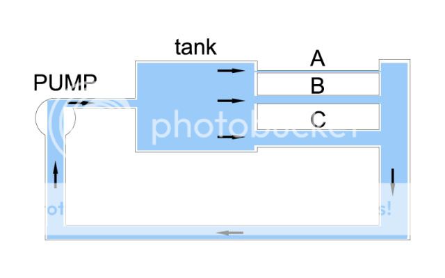
OK - not the best drawing in the world but this is what I am trying to get my head round.
The pic shows a pump feeding a tank. Out of the tank there are 3 pipes, small (A), medium (B) and large (C). The 3 pipes are connected to a common chamber which returns to the pump. A simple closed system.
What I understand is that water will take its easiest route through pipework, and in this case the easiest route is through pipe C. Yes, it will also go through B but a lower volume. Similarly, route C will also have a flow, but by comparison, a mere dribble.
From what you are saying, all 3 pipes will have an equal volume passing through them but at different velocities. This is what I can't reconcile in my tiny brain.
And yes - no argueing, just chucking ideas about
Steve
-
The Great Pretender
- Supreme Being
- Posts: 2671
- Joined: Thu Oct 19, 2006 10:10 pm
- Location: Wigan
Re: Pipe - expansion tank to heater circuit return
Will A (if not over restrictive) B and C work, singularly ,yes, will they work together? Yes if the resistance between them is equalised.
Why not concentrate on the reality of the system not hypothetical problems that probably loose most owners.
Why not concentrate on the reality of the system not hypothetical problems that probably loose most owners.
To infinity and beyond
-
Northern Bongolow

- Supreme Being
- Posts: 7713
- Joined: Mon Mar 15, 2010 11:33 pm
- Location: AKA Vanessa
Re: Pipe - expansion tank to heater circuit return
What flow you get from different size pipes in a flow test is irrelevant to flow in a sealed system.
The small pipe is not a restriction it simply alters the speed of flow, this in turn alters the pressure. Understanding the correlation between flow speed and differing pressures this creates will explain what the degassing tank is attempting to do.
thats what i attempted to say earlier, but as usuall got it slightly wrong
 .
.
in a sealed system the volumes moved in different sized pipes are all the same, the thing that alters is the speed of the flow in relation to the size of pipe, a 4 inch pipe will move 1 ltr of water in 1 min. a 2 inch pipe will move 1 litre of water in 1 miniute but it will be going at twice the speed but as a consequence the pressure in the 2 inch pipe will drop by half of the 4 inch pipe pressure.
this is how the designers have BALLANCED the flows to the required rates at certain points around the system.
of course the length of circuit and number of bends (resistance) has to be calculated into the equation also.
so back to the exp tank, the flow comes in from the rad at a fixed flow(pipe diam pump pressure ) = high pressure, carrying any air its picked up from the pump(cavitation) and any in the head/pipes, it then enters the exp tank it hits the baffles and as its a chamber the pressure drops further stalling the flow enough for the degassing to take place, but as said earlier what goes in must come out, so it is drawn out of the small bore heater return leg back towards the stat housing, now as this is a smaller bore pipe it must increase in speed,and the pressure drops, this stops air in the degassing tank being drawn back into the system towards the engine .
time for bed now my head hurts.

The small pipe is not a restriction it simply alters the speed of flow, this in turn alters the pressure. Understanding the correlation between flow speed and differing pressures this creates will explain what the degassing tank is attempting to do.
thats what i attempted to say earlier, but as usuall got it slightly wrong
in a sealed system the volumes moved in different sized pipes are all the same, the thing that alters is the speed of the flow in relation to the size of pipe, a 4 inch pipe will move 1 ltr of water in 1 min. a 2 inch pipe will move 1 litre of water in 1 miniute but it will be going at twice the speed but as a consequence the pressure in the 2 inch pipe will drop by half of the 4 inch pipe pressure.
this is how the designers have BALLANCED the flows to the required rates at certain points around the system.
of course the length of circuit and number of bends (resistance) has to be calculated into the equation also.
so back to the exp tank, the flow comes in from the rad at a fixed flow(pipe diam pump pressure ) = high pressure, carrying any air its picked up from the pump(cavitation) and any in the head/pipes, it then enters the exp tank it hits the baffles and as its a chamber the pressure drops further stalling the flow enough for the degassing to take place, but as said earlier what goes in must come out, so it is drawn out of the small bore heater return leg back towards the stat housing, now as this is a smaller bore pipe it must increase in speed,and the pressure drops, this stops air in the degassing tank being drawn back into the system towards the engine .
time for bed now my head hurts.
-
widdowson2008
- Supreme Being
- Posts: 1703
- Joined: Tue Nov 18, 2008 10:15 pm
- Location: N.E.Derbyshire
Re: Pipe - expansion tank to heater circuit return
Tanks Mel/Ady
Still don't get it and can't proove it one way or the other, so I'll just accept what you're saying as fact. Cheers for the effort.
Still don't get it and can't proove it one way or the other, so I'll just accept what you're saying as fact. Cheers for the effort.
Steve
-
haydn callow
- Supreme Being
- Posts: 5772
- Joined: Mon Jan 08, 2007 9:50 pm
- Location: Somerset
- Contact:
Re: Pipe - expansion tank to heater circuit return
Think what a venturi does.....it just speeds up the flow......big pipe to small pipe...same effect (sort of)