


ECU information required
Moderators: Doone, westonwarrior
Re: ECU information required
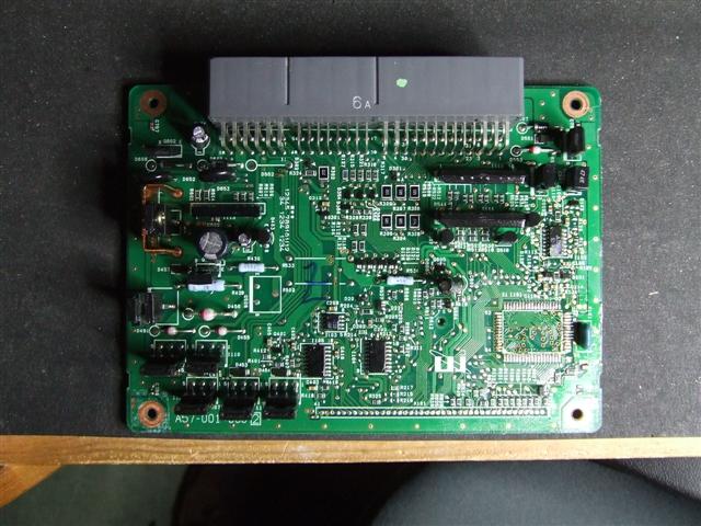
The ECU that I have is for a 2.5 TD, it looks the same as yours. PCB number is A57-001-0002, the two looks be an issue number. It is not possible to read the processor in-situ so I'm going to lash up an adapter, the processor has already been removed.
1995 Ford Freda, 2.5TD, auto, AFT, side conversion.

Re: ECU information required
The Diganostic connections are different for all three versions - WL-T, FE-E & J5-DE;
See Pages 130-135 in the 1995 models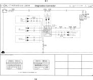 or Pages 134-139 in the 1997 models
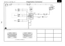
See Pages 130-135 in the 1995 models
or Pages 134-139 in the 1997 models Geoff
2001 Aero V6, AFT, full side conversion.
2001 Aero V6, AFT, full side conversion.
-
widdowson2008

- Supreme Being
- Posts: 1703
- Joined: Tue Nov 18, 2008 10:15 pm
- Location: N.E.Derbyshire
Re: ECU information required
UPDATE ON PROGRESS
What started as a quest for a simple diagram showing the pipework of the Bongo cooling system turned into a bit of a marathon. No sooner had I learned one thing, another two sprung up in its place. It seemed that the harder I tried to peer up the Bongos skirt, the more determined she was to retain a modicum of modesty and only revealed her more interesting bits with some reluctance. The whole thing mushroomed. However, with the help of members of the forum, interesting things were discovered with yet more to find out.
I think, and I stress the word ‘think’, we may be quite close to an answer. (probably should have included the word ‘hope’ in there somewhere)
We are currently digging into the ECU as this plays a pivotal role in fan control.
By piecing together (on paper at least) the ECU information and the electrical schematic diagrams into one composite picture, it has become apparent that certain circuits are activated simultaneously with others. The icing on the cake will be the actual data retrieved from the ECU memory which will put beyond any doubt as to how the operating system functions. This is being looked at by a member who doesn’t actually own a Bongo yet (Rhinoman). The prospects are looking promising.
Steve
-
mikexgough

- Supreme Being
- Posts: 6158
- Joined: Mon Sep 08, 2008 9:02 pm
- Location: Cambridgeshire - where the all the Slodgers reside
- Contact:
Re: ECU information required
I will be interested ( as you know) to see the way "The ECU Works" in respect of the Fan Control.......as there is a nagging issue I have that, I want to put to bed.....and this linked in with the cooling system stuff will put it all into perspective and satisfy my curiosity and be logged accordingly.
Conversant with Bongo Top Pinion Oil Seals
Bongo owning Velotech Cycle Mechanic
Bongo owning Velotech Cycle Mechanic
-
widdowson2008
- Supreme Being
- Posts: 1703
- Joined: Tue Nov 18, 2008 10:15 pm
- Location: N.E.Derbyshire
Re: ECU information required
Will domikexgough wrote:I will be interested ( as you know) to see the way "The ECU Works" in respect of the Fan Control.......as there is a nagging issue I have that, I want to put to bed.....and this linked in with the cooling system stuff will put it all into perspective and satisfy my curiosity and be logged accordingly.
Steve
-
mikexgough
- Supreme Being
- Posts: 6158
- Joined: Mon Sep 08, 2008 9:02 pm
- Location: Cambridgeshire - where the all the Slodgers reside
- Contact:
Re: ECU information required
I'm interested to see if it can be found at what temperature it is programmed to switch on the fans and the trigger it uses to gauge when the fans are required.... 
Conversant with Bongo Top Pinion Oil Seals
Bongo owning Velotech Cycle Mechanic
Bongo owning Velotech Cycle Mechanic
-
Grahame at work
- Bongolier
- Posts: 330
- Joined: Fri Sep 30, 2005 12:43 pm
- Location: Aberdeen
Re: ECU information required
I'm keeping my eye on this thread - it is progressing very well indeed  but I think it's time I contributed a little.
When we get the µP program / algorithms decoded it will probably give us the various thresholds / trigger values as register values. Now I’m not sure without checking how many analogue inputs there are in the system (I think there is temperature input from the gearbox) but somewhere there is going to be an A/D converter (analogue to digital). This may be a single, more than one or it may be a single multiplexed device. In order to be able to derive actual temperatures from the decoding data we need to know the calibration range of the A/D.
Can either of you look up the part numbers of likely candidates amongst the ICs on your ECUs.? I see that there are 2 ICs down the bottom of the PCB just left of centre that may be possibles but also there is circuitry above the µP that may fit the bill.
Unless the uploaded µP data has imbedded comments we (royal we that is ) may need to sketch out the analogue part of the circuit to work out the correct calibration.
Keep up the excellent work.
regards Grahame
When we get the µP program / algorithms decoded it will probably give us the various thresholds / trigger values as register values. Now I’m not sure without checking how many analogue inputs there are in the system (I think there is temperature input from the gearbox) but somewhere there is going to be an A/D converter (analogue to digital). This may be a single, more than one or it may be a single multiplexed device. In order to be able to derive actual temperatures from the decoding data we need to know the calibration range of the A/D.
Can either of you look up the part numbers of likely candidates amongst the ICs on your ECUs.? I see that there are 2 ICs down the bottom of the PCB just left of centre that may be possibles but also there is circuitry above the µP that may fit the bill.
Unless the uploaded µP data has imbedded comments we (royal we that is
Keep up the excellent work.
regards Grahame
Joanie2 has had a sex change and is remaned Bert
Re: ECU information required
The A/D is integral to the microcontroller, I posted the datasheet earlier in this thread. I haven't checked but usually the reference voltage is the 5V supply to the sensors, using that as the reference keeps the output proportional.
There will be no comments, it will be just the raw binary programming which we (most likely I) can convert to assembly language. All circuits will need to be sketched out to understand the code fully, fortunately its a fairly simple PCB and is only double-sided. I'm hoping that the manuals give some resistance values for the temperature sensors.
There will be no comments, it will be just the raw binary programming which we (most likely I) can convert to assembly language. All circuits will need to be sketched out to understand the code fully, fortunately its a fairly simple PCB and is only double-sided. I'm hoping that the manuals give some resistance values for the temperature sensors.
1995 Ford Freda, 2.5TD, auto, AFT, side conversion.
-
Grahame at work
- Bongolier
- Posts: 330
- Joined: Fri Sep 30, 2005 12:43 pm
- Location: Aberdeen
Re: ECU information required
Ok that makes life a little easier.
The reference may well be 5V - from memory the 20C voltage was about 4 volts. But I did note that the 'bottom' end of the sensor is not zero - it's just a little above, probably to clear the minimum offset for the A/D (probably why its a two terminal sensor) and I think it shares this node with other circuits.
The manual does give resistance readings for 2 points but not sufficient to give a top end calibration. However, it does give a temperature value for the trigger point for operating the high speed fans so given the µP data it should be possible to ‘fix’ the top end.
Regards Grahame
Joanie2 has had a sex change and is remaned Bert
Re: ECU information required
Sensor voltages are usually scaled so that they don't go the full range of the input, this is for diagnostics so that open circuit or short circuit conditions can be detected. On the more sophisticated ECUs the reference ground is also measured.
1995 Ford Freda, 2.5TD, auto, AFT, side conversion.
-
mikexgough
- Supreme Being
- Posts: 6158
- Joined: Mon Sep 08, 2008 9:02 pm
- Location: Cambridgeshire - where the all the Slodgers reside
- Contact:
Re: ECU information required
Conversant with Bongo Top Pinion Oil Seals
Bongo owning Velotech Cycle Mechanic
Bongo owning Velotech Cycle Mechanic
-
widdowson2008
- Supreme Being
- Posts: 1703
- Joined: Tue Nov 18, 2008 10:15 pm
- Location: N.E.Derbyshire
Re: ECU information required
As you get your sketches together in rough form, if you can scan/email them to me, I will produce pucker drawings to go together with what I am already doing.Rhinoman wrote:The A/D is integral to the microcontroller, I posted the datasheet earlier in this thread. I haven't checked but usually the reference voltage is the 5V supply to the sensors, using that as the reference keeps the output proportional.
There will be no comments, it will be just the raw binary programming which we (most likely I) can convert to assembly language. All circuits will need to be sketched out to understand the code fully, fortunately its a fairly simple PCB and is only double-sided. I'm hoping that the manuals give some resistance values for the temperature sensors.
ps. aint got a clue what you guys are talking about but it sounds good.
Steve
Re: ECU information required
I 'sketch' out the circuits using a PCB design software package. I say sketch because I don't usually bother ensuring that I use the correct symbols for resistor sizes and I don't fill in all the values. Now I get my bills electronically I find myself short of envelopes 
I need to make an adapter PCB to read the processor, I was hoping to use an off the shelf adapter but its an odd pitch. That won't be ready until some time next week.
I need to make an adapter PCB to read the processor, I was hoping to use an off the shelf adapter but its an odd pitch. That won't be ready until some time next week.
1995 Ford Freda, 2.5TD, auto, AFT, side conversion.
Re: ECU information required
I haven't forgotten this, I'm going to Morocco tomorrow but I'll be on this when I get back next week. I'll also be actively hunting for a Bongo for myself (AFT, side conversion, R&R bed, 4WD).
1995 Ford Freda, 2.5TD, auto, AFT, side conversion.
Re: ECU information required
Have a good trip ! I see Steve hasn't been around for a few days, trust he's OK.
Geoff
2001 Aero V6, AFT, full side conversion.
2001 Aero V6, AFT, full side conversion.