Page 10 of 41
Re: coolant flow - (follow up to cooling diagram)
Posted: Wed Feb 17, 2010 3:11 pm
by widdowson2008
Ian wrote:Steve, I have some genuine Mazda thermostats on order, give me a ring this time next week and I will donate one to the cause, and you can pull it apart etc etc......

Hi Ian
Does this mean you will be stocking the genuine Mazda stat AS WELL AS the Blueprint, or INSTEAD OF?
Re: coolant flow - (follow up to cooling diagram)
Posted: Wed Feb 17, 2010 3:12 pm
by Ian
As well as.
Re: coolant flow - (follow up to cooling diagram)
Posted: Wed Feb 17, 2010 8:19 pm
by missfixit70
Took this photo while I was under the bongo
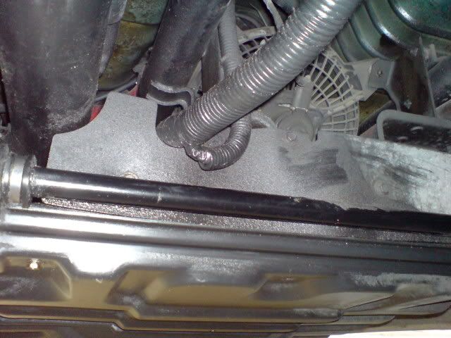
shows a vertical "baffle" running the width of the front tray approximately 4-5" high, just thought you may want to throw that into the mix Steve

Re: coolant flow - (follow up to cooling diagram)
Posted: Wed Feb 17, 2010 8:34 pm
by maxheadroom
widdowson2008 wrote:maxheadroom wrote: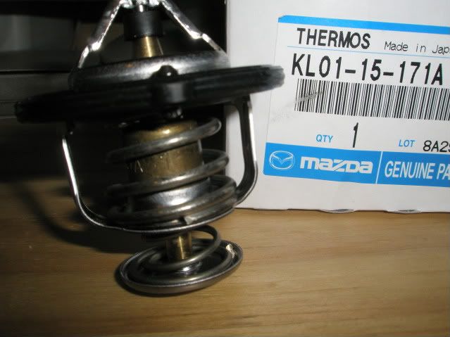
The other difference is (and this may be an optical illusion) the brass bit that butts up to the seal appears to be tapered (perhaps Max could confirm)
Yes it is tapered.

Re: coolant flow - (follow up to cooling diagram)
Posted: Wed Feb 17, 2010 11:08 pm
by widdowson2008
maxheadroom wrote:widdowson2008 wrote:maxheadroom wrote:
The other difference is (and this may be an optical illusion) the brass bit that butts up to the seal appears to be tapered (perhaps Max could confirm)
Yes it is tapered.
Thanks Nic
So the Mazda stat HAS differences - and that's only external.
Wonder what's inside.


Y'know, I have been in the wrong job all these years - shoulda been a surgeon
Re: coolant flow - (follow up to cooling diagram)
Posted: Wed Feb 17, 2010 11:42 pm
by widdowson2008
missfixit70 wrote:
Took this photo while I was under the bongo
shows a vertical "baffle" running the width of the front tray approximately 4-5" high, just thought you may want to throw that into the mix Steve
Modified as per Kirsty (I hope)

Re: coolant flow - (follow up to cooling diagram)
Posted: Thu Feb 18, 2010 9:28 am
by mikexgough
I like the airflow drawing Steve..... perhaps I am ahead of the game here but it seems to lend itself to suggest that the radiator uses a lot of it's convection properties for cooling as the main airflow to the engine radiator appears to be at the bottom of the radiator with a smaller flow from the top of the radiator down to the main Air flow over the engine .......just an observation..... especially when you take in to the equation the shape/size of the fan cowlings restricting air flow through the radiator........just a thought
Re: coolant flow - (follow up to cooling diagram)
Posted: Thu Feb 18, 2010 10:20 am
by widdowson2008
mikexgough wrote:I like the airflow drawing Steve..... perhaps I am ahead of the game here but it seems to lend itself to suggest that the radiator uses a lot of it's convection properties for cooling as the main airflow to the engine radiator appears to be at the bottom of the radiator with a smaller flow from the top of the radiator down to the main Air flow over the engine .......just an observation..... especially when you take in to the equation the shape/size of the fan cowlings restricting air flow through the radiator........just a thought
Steady on Mike.......
This diagram was produced some time ago. Kirsty dug it up because...................well..............does Kirsty need a reason to dig things up
. She had been under her Bongo and taken the pic of the baffle, posted it, and I corrected the drawing (hopefully) in line with her findings.
The drawing was originally made to indicate that the air flow is a significant part of the part of the cooling system cycle.
It hopefully indicates that whilst the van is in motion, the throughdraft of air flows over the radiator and through the engine compartment. When the van is stopped (at traffic lights/traffic jam, etc) this flow of air will stop, causing the engine to get hotter, until it reaches a point (probably somewhere at the top end of the thermostat control band) where the ECU cuts in the rad fans (to lower the coolant temperature level) and the scavenger fan (to reduce the engin bay temperature)
Re: coolant flow - (follow up to cooling diagram)
Posted: Thu Feb 18, 2010 12:42 pm
by mikeonb4c
My two penneth worth would be to say that the biggest design factors influencing convection would I reckon be:
* the surface area to volume ratio of the hot body (rad+contents - in practical terms how many thin pipes and thin cooling fins connected to them)
* the ease with which the rising hot air can escape / be drawn away by the conveciton process (in practical terms how freely air can flow through the pipe/fin matrix, and how easily the rising air can escape so as enable rapid replacement with cold air from e.g. underneath the radiator.
The best chance of something approaching the effect of a chimney might be hot air hitting the angled bonnet underside and moving up and back to exit the gap at the back of the bonnet. This would encourage cool air to be drawn in through the radiator grille to complement air being pulled up from beneath. But all that is just a guess and would need checking by taking readings, making observations etc.
I wonder what the baffle in Kirstys pic is about. Maybe there to protect the engine bay from stuff thrown up by the road? It might also be a bit beneficial when convection only is at work by reducing pre-warming of cool air through black body radiation from the main engine mass as well as encouraging airmass to 'chimney up' through the radiator opening. But I think that's really starting to push the bounds of credibility where the thoughts of the designers are concerned

Some experiments with smoke sources, to trace path taken by airmass, could be rather good fun.

Re: coolant flow - (follow up to cooling diagram)
Posted: Thu Feb 18, 2010 12:46 pm
by missfixit70
The baffle is nowhere near the rad, it's behind the front wheels, so there would be no relation between it the rad, I think it's probably just there as a crap deflector.
Re: coolant flow - (follow up to cooling diagram)
Posted: Thu Feb 18, 2010 1:44 pm
by dandywarhol
Whats with all the silver paint Mizzie? some kind of heat deflection theory
Re: coolant flow - (follow up to cooling diagram)
Posted: Thu Feb 18, 2010 1:54 pm
by missfixit70
dandywarhol wrote:Whats with all the silver paint Mizzie? some kind of heat deflection theory
It's actually black & a bit oily, just the reflection
Re: coolant flow - (follow up to cooling diagram)
Posted: Thu Feb 18, 2010 2:23 pm
by widdowson2008
missfixit70 wrote:The baffle is nowhere near the rad, it's behind the front wheels, so there would be no relation between it the rad, I think it's probably just there as a crap deflector.
My thoughts too. However, if it were NOT there, the air would go straight through (underneath the engine) wouldn't it? By having it there, I would think it encourages the air flow upward toward the engine? Just an observation
Re: coolant flow - (follow up to cooling diagram)
Posted: Thu Feb 18, 2010 2:26 pm
by mikeonb4c
missfixit70 wrote:The baffle is nowhere near the rad, it's behind the front wheels, so there would be no relation between it the rad, I think it's probably just there as a crap deflector.
Black body radiation travels, so just as with visible radiation (like the beam from a torch), if the rad or the air between it and the 'torch' can see it, it gets light (heated) up. But I'm sure your right - its really there just as a crud shield. Mind you, 'every little helps' as Tesco like to remind us.
Re: coolant flow - (follow up to cooling diagram)
Posted: Thu Feb 18, 2010 7:43 pm
by missfixit70
There is all sorts of other stuff in the way to soak up any possible heat radiated back towards the engine from the rad Mike, including an intercooler, steering rack, etc, don't forget there's also a cowling aroung the back of the rad too. Ain't no blackbodies radiating down there
