


ECU information required
Moderators: Doone, westonwarrior
Re: ECU information required
The component marked 102 is a resister (1KOhm). All the resistors marked 153 look to be connected together so I think that we can discount these for now, they are most likely just pull-up resistors going to 5V. I would expect the main circuits to go through the 1K resistors.
1995 Ford Freda, 2.5TD, auto, AFT, side conversion.
-
widdowson2008

- Supreme Being
- Posts: 1703
- Joined: Tue Nov 18, 2008 10:15 pm
- Location: N.E.Derbyshire
Re: ECU information required
Trace result for pins 11 and 12.
They go to the 'black thingies' marked 'X' at the bottom left (chip side) of the pcb - if I have it correct, they both err toward the right hand side of each 'black thingy'. Perhaps you would enlighten me as to precisely what a 'black thingy' is.

They go to the 'black thingies' marked 'X' at the bottom left (chip side) of the pcb - if I have it correct, they both err toward the right hand side of each 'black thingy'. Perhaps you would enlighten me as to precisely what a 'black thingy' is.
Steve
Re: ECU information required
The black things are transistors. Can you read the numbers on them?
1995 Ford Freda, 2.5TD, auto, AFT, side conversion.
-
widdowson2008
- Supreme Being
- Posts: 1703
- Joined: Tue Nov 18, 2008 10:15 pm
- Location: N.E.Derbyshire
Re: ECU information required
Eyes aren't quite what they used to be and very difficult to see (minute)
Number looks like 5154S
Does that ring any bells?
Number looks like 5154S
Does that ring any bells?
Steve
Re: ECU information required
That is a PNP transistor with built in protection and diagnostic feedback. Have they both got the same number?
http://www.rhinopower.org/ECUs/Bongo/do ... 54S_ds.pdf
http://www.rhinopower.org/ECUs/Bongo/do ... 54S_ds.pdf
1995 Ford Freda, 2.5TD, auto, AFT, side conversion.
-
widdowson2008
- Supreme Being
- Posts: 1703
- Joined: Tue Nov 18, 2008 10:15 pm
- Location: N.E.Derbyshire
Re: ECU information required
Impossible to see without bending something. The number is etched low down, near the board, and is tucked behind the one directly in front of it.widdowson2008 wrote:Trace result for pins 11 and 12.
However, the one to the right of No.12, (under the actual No12 number) is marked 5151S.
I know this isn't what you asked, but the reason I got it was to show that whilst they all look the same physically, they are not all necessarily the same number.
Where do you want me to go from here? Is the number critical to your investigation?
Steve
Re: ECU information required
SI-5151S is very similar to the 5154S. So far the circuitry isn't what I was expecting nut it may just be that JECS do things differently. I think we should wait and see if I manage to get that ECU.
Thanks
James
Thanks
James
1995 Ford Freda, 2.5TD, auto, AFT, side conversion.
-
widdowson2008
- Supreme Being
- Posts: 1703
- Joined: Tue Nov 18, 2008 10:15 pm
- Location: N.E.Derbyshire
Re: ECU information required
Would you keep me informed of progress please? and let me know if there is anything I can do.Rhinoman wrote:SI-5151S is very similar to the 5154S. So far the circuitry isn't what I was expecting nut it may just be that JECS do things differently. I think we should wait and see if I manage to get that ECU.
Thanks
James
Steve
-
widdowson2008
- Supreme Being
- Posts: 1703
- Joined: Tue Nov 18, 2008 10:15 pm
- Location: N.E.Derbyshire
Re: ECU information required
Can anyone tell me what each of the folowing symbols represent? and what they actually do?
For example, I know that item 2 is the ignition switch, and appears to have 4 positions, but what do those positions represent?
Some of the symbols may get complicated so if you could aim any replies at the dummy level, I would appreciate it.
Thank you.

For example, I know that item 2 is the ignition switch, and appears to have 4 positions, but what do those positions represent?
Some of the symbols may get complicated so if you could aim any replies at the dummy level, I would appreciate it.
Thank you.
Steve

Re: ECU information required
OK going from top left;widdowson2008 wrote:Can anyone tell me what each of the folowing symbols represent? and what they actually do?
For example, I know that item 2 is the ignition switch, and appears to have 4 positions, but what do those positions represent?
Some of the symbols may get complicated so if you could aim any replies at the dummy level, I would appreciate it.
Thank you.
1. Fuses, X-01 are in the Battery terminal case, X-02 are in the central box, X-03 are the ones by the drivers knee .
2. X-04 is the Ignition switch, shown in the OFF position.
3. A relay, single pole.
4. Fan motor,this is a bit special as it has 4 brushes not the normal 2 brushes, they give different speeds when used in conjunction with each other.
5. A simple switch, single pole.
6. The switch connected to the gear shift. Single pole, 6 positions.
7. A solenoid with an iron core.
8. Solenoids or coils 5 of them in a single module, with a variable resistor at the right hand end.
9. A potentiometer - similar to a variable resistor, but not the same.
10. A solenoid or coil.
11. Another relay just drawn mirrored to the previous one, single pole.
12. 4 resistors in a single module - in this case its actually the Glow plugs - a slightly strange way of drawing them as a single module !
13. A switch with indicator lamp built in.
14. A module with a solenoid, switch, variable resistor and a potentiometer.
As to what each does will take a while to explain - and to some extent depends on where or how they are used! I'll see what I can put together later.
Geoff
2001 Aero V6, AFT, full side conversion.
2001 Aero V6, AFT, full side conversion.
Re: ECU information required
OK after lunch, what does what;
1. Fuses - They are there to protect the cable from catching fire if a short circuit occurs - they DON'T protect the device on the end of the cable.
2. Ignition Switch - This has a Single common connection - hence Single Pole - the common connection is at the Top centre of the image, from the common connection is a Wiper which moves as the key is turned - that's the line with an arrow head in the 4 O'Clock position OFF, turn the key clockwise to the first position ACC -Ancillaries at the 5 O'Clock position this powers up the radio, Cigar lighters etc. The next position is the normal running position - IG2 at 7 O'Clock, power is connected to the engine circuits etc., the link back to the ACC position (diagonal internal connection) means that the Radio etc. keeps working in the IG2 position. The final position is the STarter position at 8 O'Clock, the Ancillaries are turned off to protect them whilst the starter motor is active (Big high voltage spikes), the internal link keeps the engine circuits powered up, on release the final position is spring loaded and the switch will return to the IG2 position.
3. Relay a device for controlling higher power circuits or isolating one circuit from another - the symbol has two parts a switch or contacts and a coil. Pass a current thru the coil and the magnetic field pulls the switch/contacts into a different position making and breaking circuits. The symbol shown would normally indicate a Single Pole, Normally Open, when a current passes thru the coil then the contacts make contact i.e. the contacts closed position. On some diagrams it is often difficult to work out if a set of contacts are Normally Open or Normally Closed - its best NOT to make an assumption but work out what should be happening!
OK more later - time for a cup of coffee
Geoff
2001 Aero V6, AFT, full side conversion.
2001 Aero V6, AFT, full side conversion.
Re: ECU information required
Right Coffee to hand;
4. Special case ! be warned.
Generally this symbol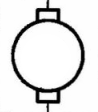 means a rotating device with two brush type connections.
A letter or symbol inside the circle indicates the type of device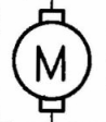 in this case a Motor
or maybe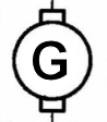 a Generator or perhaps
  a Pump.
In the case of it means that there are 4 Brushes and in this case its one of the radiator fans, these have two sets of connections to give multiple speeds - you can't tell from the symbol if its just Off & two speeds of if by using both connections at the same time you end up with a total of Off and three speeds.
5. A simple switch, its difficult to tell from the symbol if its a Normally Open switch that Closes on Operation or if its Normally Closed and Opens on operation, sometimes the symbol isn't intended to make the distinction sometimes it is so its best NOT to assume anything but try to work out from the physical device or the circuit when its Open and when its Closed - sometimes "normal" doesn't have much of a meaning anyway it just has two positions and that's all that can be said.
6. Another switch again one common connection so Single Pole, but has 6 ways (positions) - in this case its the Automatic Gear Stick which has 6 positions, its shown in the Park position and the wiper moves to Reverse / Neutral / Drive etc.
4. Special case ! be warned.
Generally this symbol
means a rotating device with two brush type connections.A letter or symbol inside the circle indicates the type of device
in this case a Motoror maybe
a Generator or perhaps a Pump.In the case of
it means that there are 4 Brushes and in this case its one of the radiator fans, these have two sets of connections to give multiple speeds - you can't tell from the symbol if its just Off & two speeds of if by using both connections at the same time you end up with a total of Off and three speeds.5. A simple switch, its difficult to tell from the symbol if its a Normally Open switch that Closes on Operation or if its Normally Closed and Opens on operation, sometimes the symbol isn't intended to make the distinction sometimes it is
6. Another switch again one common connection so Single Pole, but has 6 ways (positions) - in this case its the Automatic Gear Stick which has 6 positions, its shown in the Park position and the wiper moves to Reverse / Neutral / Drive etc.
Geoff
2001 Aero V6, AFT, full side conversion.
2001 Aero V6, AFT, full side conversion.
Re: ECU information required
Right lets take items 7 and 10 together;
These are solenoids or basically coils of wire - if it has a pair of solid lines then that means its wound on an iron core - the purpose of the coil is to generate or detect a magnetic field, the iron core helps make the field stronger, solenoids come in all shapes and sizes. In the Bongo they are used for a variety of purposes from controlling vanes in the air conditioning system to operating the levers in the transmission system. They can also be used to detect magnetic fields to indicate timing and position information - as normal just what a particular device is doing depends on the circuit its in.
8. This is a module with several things in this case 5 coils and a variable resistor - the fact that the variable resistor (righthand end) has ATF in its description suggests that it is involved with the Automatic Transmission Fluid - possibly a temperature sensor ( although normally temperature sensors have a black or white dot (+ve / -ve temperature co-efficient) rather than an arrow) it could just be a sensor which sends back the analogue position of a spindle or control. The five coils maybe the solenoid pack that controls the gearbox - it really needs to be associated with the physical diagrams in the Lush project to be sure !
It looks like your reffering to B2-21;
Electrical here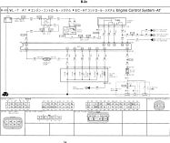 located here B2-21
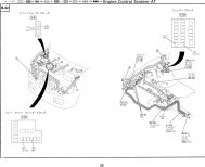 which tallies with the Lush Project Transmission bits available from here! I'll leave it to the Mech. engineers to say how it physically works!
These are solenoids or basically coils of wire - if it has a pair of solid lines then that means its wound on an iron core - the purpose of the coil is to generate or detect a magnetic field, the iron core helps make the field stronger, solenoids come in all shapes and sizes. In the Bongo they are used for a variety of purposes from controlling vanes in the air conditioning system to operating the levers in the transmission system. They can also be used to detect magnetic fields to indicate timing and position information - as normal just what a particular device is doing depends on the circuit its in.
8. This is a module with several things in this case 5 coils and a variable resistor - the fact that the variable resistor (righthand end) has ATF in its description suggests that it is involved with the Automatic Transmission Fluid - possibly a temperature sensor ( although normally temperature sensors have a black or white dot (+ve / -ve temperature co-efficient) rather than an arrow) it could just be a sensor which sends back the analogue position of a spindle or control. The five coils maybe the solenoid pack that controls the gearbox - it really needs to be associated with the physical diagrams in the Lush project to be sure !
It looks like your reffering to B2-21;
Electrical here
located here B2-21which tallies with the Lush Project Transmission bits available from here! I'll leave it to the Mech. engineers to say how it physically works!Geoff
2001 Aero V6, AFT, full side conversion.
2001 Aero V6, AFT, full side conversion.
Re: ECU information required
I have four pages of schematics from Widdowson2008.
Page B-2a is parts related to engine control functions including EGR and Glow plugs, I'm curious about the two coils marked FICD.
Page B-2b appears to have an EGR temperature sensor, the two iron cored solenoids (functions?) and some other parts (?)
Page B-2c is the auto transmission related functions
Page B-6 is the the functions relating to the fans
1995 Ford Freda, 2.5TD, auto, AFT, side conversion.
Re: ECU information required
There are two types of variable resistor shown here, I suspect that the ATF variable resistor is a thermistor as you suggest. The other type is shown on B-2b and is marked EGR, I suspect that this is a potentiometer used to determine EGR position.g8dhe wrote: 8. This is a module with several things in this case 5 coils and a variable resistor - the fact that the variable resistor (righthand end) has ATF in its description suggests that it is involved with the Automatic Transmission Fluid - possibly a temperature sensor ( although normally temperature sensors have a black or white dot (+ve / -ve temperature co-efficient) rather than an arrow) it could just be a sensor which sends back the analogue position of a spindle or control.
Last edited by Rhinoman on Fri Jan 15, 2010 4:51 pm, edited 1 time in total.
1995 Ford Freda, 2.5TD, auto, AFT, side conversion.