


AFAIK they enhance tube side heat transfer efficiency... as far as I know.......and what do the 'twisties' actually do? cos mine's got 'em too.
coolant flow - (follow up to cooling diagram)
Moderators: Doone, westonwarrior
Re: coolant flow - (follow up to cooling diagram)
Allans Garage retired. Try PGS (Plymouth Garage Services) or Mayflower Auto Services Plymouth

Re: coolant flow - (follow up to cooling diagram)
They cause the water to flow in a turbulent manner, rather than a laminar flow, this means that you get better heat transfer. If its a laminar flow then the water closest to the metal flows slower and very smoothly and "insulates" the water further from the metal and hence slows down heat transfer. Turbulent flow means you get little swirls and ripples which in turn means all the water gets to cool down / transfer heat evenly.widdowson2008 wrote:..and what do the 'twisties' actually do? cos mine's got 'em too.
Geoff
2001 Aero V6, AFT, full side conversion.
2001 Aero V6, AFT, full side conversion.
-
widdowson2008

- Supreme Being
- Posts: 1703
- Joined: Tue Nov 18, 2008 10:15 pm
- Location: N.E.Derbyshire
Re: coolant flow - (follow up to cooling diagram)
Yep - go along with both those answers for no other reason they are logical and make total sense. 
Just got the physical shape/dimensions from Helen (who is getting a pic for me tomorrow). Apparently, they are flat - we'll see. ....to be continued.
.....moving on.......
In the process of chopping further to find the next answer (probably find out tomorrow), but I'll throw it in for suggestions anyway. Both the inlet and outlet are on the same side whilst the tubes are horizontal. Question is, how does coolant flow horizontally, yet come back to the same side of the heater?
ps Keep it up Helen
Steve
-
mikexgough

- Supreme Being
- Posts: 6158
- Joined: Mon Sep 08, 2008 9:02 pm
- Location: Cambridgeshire - where the all the Slodgers reside
- Contact:
Re: coolant flow - (follow up to cooling diagram)
Happy to research the parts and source supplies of the O.E parts in the makers packaging .....be a long job and may need help with some part numbers off of the "Mazda" parts .....mainly from the bodies of them not the Mazzy factory part numberswiddowson2008 wrote:Don't think it would be quite that simple a task TBH Ron. Take the stat for example. On the surface, the pattern stat looks identical to a Mazda one, but like the Heinz/Sainsbury ketchup analogy, it's the missing ingedient that makes the difference.
When pattern parts are made, they are generally produced to the same specification as the original - material, tolerances, etc. The pattern stat is different in (at least) one aspect. It has the extra stem seal which makes it (IMHO) the better (though more expensive) option.
Whoever took on this task would need to be able to SPOT the difference(s) - a time consuming excercise.
Conversant with Bongo Top Pinion Oil Seals
Bongo owning Velotech Cycle Mechanic
Bongo owning Velotech Cycle Mechanic
-
widdowson2008
- Supreme Being
- Posts: 1703
- Joined: Tue Nov 18, 2008 10:15 pm
- Location: N.E.Derbyshire
Re: coolant flow - (follow up to cooling diagram)
That would be a job WELL worth doing Mike.mikexgough wrote: Happy to research the parts and source supplies of the O.E parts in the makers packaging .....be a long job and may need help with some part numbers off of the "Mazda" parts .....mainly from the bodies of them not the Mazzy factory part numbers......
If I can be of any help, then all you need to do is to ask.
Because this is important, I think it should be done under a topic in its own right (ie: another thread), for two reasons:
1 - It risks being burried within a thread such as this one and a REAL pain to find when needed.
2 - It would avoid defragmentation of the 'host' thread. ie: losing the thread of the thread, (if you know what I mean)
Gonna start one Mike?
Steve
-
helen&tony

- Supreme Being
- Posts: 9869
- Joined: Thu Nov 18, 2004 12:49 pm
- Location: Bulgaria
Re: coolant flow - (follow up to cooling diagram)
Hi
The "Further Choppings" will happen tomorrow...and the plastic thingies aren't like Dandy's one
Geoff...you get the star prize...LAMINAR FLOW...Don't ask, or I'll bore you till Hell freezes over on that one
Cheers
Helen
The "Further Choppings" will happen tomorrow...and the plastic thingies aren't like Dandy's one
Geoff...you get the star prize...LAMINAR FLOW...Don't ask, or I'll bore you till Hell freezes over on that one
Cheers
Helen
In the beginning there was nothing , then God said "Let there be Light".....There was still nothing , but ,by crikey, you could see it better.
Re: coolant flow - (follow up to cooling diagram)
Perhaps the inlet tube is blocked half way along, so the water has to flow up thru the fins to the top pipe, then back down the other side, so half of the fins have water flowing up them and half have the water flowing down them back to the outlet ?widdowson2008 wrote:Question is, how does coolant flow horizontally, yet come back to the same side of the heater?
Geoff
2001 Aero V6, AFT, full side conversion.
2001 Aero V6, AFT, full side conversion.
-
widdowson2008
- Supreme Being
- Posts: 1703
- Joined: Tue Nov 18, 2008 10:15 pm
- Location: N.E.Derbyshire
Re: coolant flow - (follow up to cooling diagram)
g8dhe wrote:Perhaps the inlet tube is blocked half way along, so the water has to flow up thru the fins to the top pipe, then back down the other side, so half of the fins have water flowing up them and half have the water flowing down them back to the outlet ?widdowson2008 wrote:Question is, how does coolant flow horizontally, yet come back to the same side of the heater?
Sorry Geoff - must be me but I cant picture that..........Sketch needed
Steve
Re: coolant flow - (follow up to cooling diagram)
OK found this picture which I have drawn on;
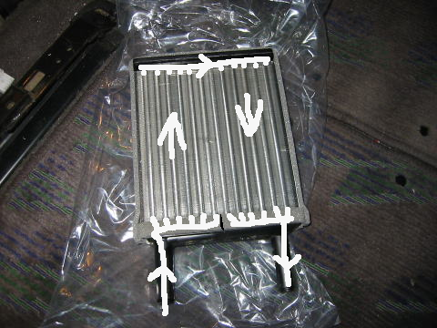
Geoff
2001 Aero V6, AFT, full side conversion.
2001 Aero V6, AFT, full side conversion.
-
dandywarhol

- Supreme Being
- Posts: 5446
- Joined: Mon Dec 19, 2005 10:18 pm
- Location: Edinburgh
Re: coolant flow - (follow up to cooling diagram)
don't know what it's from - just found it on the 'netwiddowson2008 wrote:dandywarhol wrote: And a pic of a discected matrix - the "twisties" are known as turbulators in the industry
OK - Just got my own pics from Helen of a dissected front heater. BLOODY FASCINATING to say the least.
Requested Helen to do even MORE cuts as the flow path isn't apparent (to me at least.)
Also asked for physical sizes so I can put some numbers around it.
Didn't realise at the time Dandy posted the above pic, but it looks very similar to the ones I have. Is that one from a Bongo Dandy?Just checked - don't think it is from a Bongo - less tubes (unless this is a rear heater?)
......and what do the 'twisties' actually do? cos mine's got 'em too.
I'LL BE BACK.
BTW - keep that up Ady - should make an interesting read
Will this ever end mother?
Whale oil beef hooked
Renault Lunar Telstar
Yamaha TD1C 250, Merc SLK200, KTM Duke 690
Renault Lunar Telstar
Yamaha TD1C 250, Merc SLK200, KTM Duke 690
-
widdowson2008
- Supreme Being
- Posts: 1703
- Joined: Tue Nov 18, 2008 10:15 pm
- Location: N.E.Derbyshire
Re: coolant flow - (follow up to cooling diagram)
Thanks Dandy.dandywarhol wrote:
don't know what it's from - just found it on the 'net
Have you seen the flow that Geoff posted? Now that is starting to make a bit of sense
Geoff
How did you arrive at that path? Was it a guesstimate? or do you know summat I don't? Certainly looks a possible goer.
Having said that, it isn't quite the same shape (inlet/outlet pipes). Is this a pattern part?
Should have rest of info from Helen sometime tomorrow, and I'll post some pics of conclusions.
You have no idea how frustrating it is not to be able to do the cuts myself and get my hands on it.
Steve
-
The Great Pretender

- Supreme Being
- Posts: 2671
- Joined: Thu Oct 19, 2006 10:10 pm
- Location: Wigan
Re: coolant flow - (follow up to cooling diagram)
Good luck with it, I considered something similar but as my coolant system has been altered a donor Bongo would have been needed.Northern Bongolow wrote:thanks guysthe main reason im asking is because im making this pressure monitoring gadget.
it will measure bottom end and top end pressures of the coolant system.
i was hoping to use the bottom end measurment (if its a positive pressure ) as a form of coolant leak alarm,both pressure switches are variable,so it should be of some good.it should still give an early warning of top end pressure problems,so i will bash on regardless.
just one problem that ive just managed to overcome,i bought galvanized fittings initially,but as ive found out that my red coolant attacks galv ive had to resource but im there now i think
I was thinking along the lines of a single pressure thingy in the tank working against a temp sensor (if then scenario). As the only pressure build up is temp related correlation should not be a problem as in above or below expected. EG below pressure a leak, above, stat, blockage or trapped air problem.
To infinity and beyond
-
The Great Pretender
- Supreme Being
- Posts: 2671
- Joined: Thu Oct 19, 2006 10:10 pm
- Location: Wigan
Re: coolant flow - (follow up to cooling diagram)
Yes they do, also as there is no way to vent the heaters they will increase the speed through the small bore pipes reducing the size of any air to suspended proportions then hopefully evacuating them.Doone wrote:AFAIK they enhance tube side heat transfer efficiency... as far as I know.......and what do the 'twisties' actually do? cos mine's got 'em too.
To infinity and beyond
-
The Great Pretender
- Supreme Being
- Posts: 2671
- Joined: Thu Oct 19, 2006 10:10 pm
- Location: Wigan
Re: coolant flow - (follow up to cooling diagram)
Now Steve your being a lil naughty, we have to understand your pics, spend a lil time and look at it.widdowson2008 wrote:Thanks Dandy.dandywarhol wrote:
don't know what it's from - just found it on the 'net
Have you seen the flow that Geoff posted? Now that is starting to make a bit of sense
Geoff
How did you arrive at that path? Was it a guesstimate? or do you know summat I don't? Certainly looks a possible goer.
Having said that, it isn't quite the same shape (inlet/outlet pipes). Is this a pattern part?
Should have rest of info from Helen sometime tomorrow, and I'll post some pics of conclusions.
You have no idea how frustrating it is not to be able to do the cuts myself and get my hands on it.
The collectors at the base are split in two, left half in, right half out, turn it 90deg anti clockwise and it will self vent.
To infinity and beyond
-
widdowson2008
- Supreme Being
- Posts: 1703
- Joined: Tue Nov 18, 2008 10:15 pm
- Location: N.E.Derbyshire
Re: coolant flow - (follow up to cooling diagram)
Hi TGP
Just come back from studying the pics and producing a drawing (to scale of course), and I had worked that out myself. But thanks for beating me to it. You're on the ball.
This provides the final piece (the only one I never fully understood) of the bleeding fiasco neatly into place, PROVIDING (for me) that Helen comes back and cofirms the through route, which I suspect she might.
I now fully understand the whys of the belching and farting that goes on in the bleed process and where air will, and will not, get trapped. It's a GOOD feeling.
I also have accurate pipe sizes, and therefore volumes.
The pipework in the Mazda matrix is constructed from thin walled aluminium and looks quite delicate. Having said that, the pipe bores look very clean.
Will publish findings ASAP.
Steve