Re: coolant flow - (follow up to cooling diagram)
Posted: Wed Nov 24, 2010 2:58 pm
AFAIK they enhance tube side heat transfer efficiency... as far as I know.......and what do the 'twisties' actually do? cos mine's got 'em too.
A forum for Bongo fans and owners
https://www.igmaynard.co.uk/bongo/forum/
https://www.igmaynard.co.uk/bongo/forum/viewtopic.php?t=36433
AFAIK they enhance tube side heat transfer efficiency... as far as I know.......and what do the 'twisties' actually do? cos mine's got 'em too.
They cause the water to flow in a turbulent manner, rather than a laminar flow, this means that you get better heat transfer. If its a laminar flow then the water closest to the metal flows slower and very smoothly and "insulates" the water further from the metal and hence slows down heat transfer. Turbulent flow means you get little swirls and ripples which in turn means all the water gets to cool down / transfer heat evenly.widdowson2008 wrote:..and what do the 'twisties' actually do? cos mine's got 'em too.
Happy to research the parts and source supplies of the O.E parts in the makers packaging .....be a long job and may need help with some part numbers off of the "Mazda" parts .....mainly from the bodies of them not the Mazzy factory part numberswiddowson2008 wrote:Don't think it would be quite that simple a task TBH Ron. Take the stat for example. On the surface, the pattern stat looks identical to a Mazda one, but like the Heinz/Sainsbury ketchup analogy, it's the missing ingedient that makes the difference.
When pattern parts are made, they are generally produced to the same specification as the original - material, tolerances, etc. The pattern stat is different in (at least) one aspect. It has the extra stem seal which makes it (IMHO) the better (though more expensive) option.
Whoever took on this task would need to be able to SPOT the difference(s) - a time consuming excercise.
That would be a job WELL worth doing Mike.mikexgough wrote: Happy to research the parts and source supplies of the O.E parts in the makers packaging .....be a long job and may need help with some part numbers off of the "Mazda" parts .....mainly from the bodies of them not the Mazzy factory part numbers......
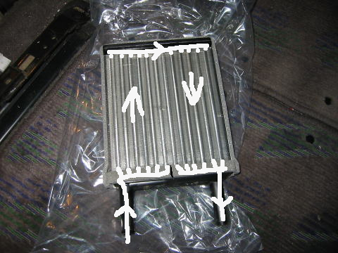
Perhaps the inlet tube is blocked half way along, so the water has to flow up thru the fins to the top pipe, then back down the other side, so half of the fins have water flowing up them and half have the water flowing down them back to the outlet ?widdowson2008 wrote:Question is, how does coolant flow horizontally, yet come back to the same side of the heater?
g8dhe wrote:Perhaps the inlet tube is blocked half way along, so the water has to flow up thru the fins to the top pipe, then back down the other side, so half of the fins have water flowing up them and half have the water flowing down them back to the outlet ?widdowson2008 wrote:Question is, how does coolant flow horizontally, yet come back to the same side of the heater?
don't know what it's from - just found it on the 'netwiddowson2008 wrote:dandywarhol wrote: And a pic of a discected matrix - the "twisties" are known as turbulators in the industry
OK - Just got my own pics from Helen of a dissected front heater. BLOODY FASCINATING to say the least.
Requested Helen to do even MORE cuts as the flow path isn't apparent (to me at least.)
Also asked for physical sizes so I can put some numbers around it.
Didn't realise at the time Dandy posted the above pic, but it looks very similar to the ones I have. Is that one from a Bongo Dandy?Just checked - don't think it is from a Bongo - less tubes (unless this is a rear heater?)
......and what do the 'twisties' actually do? cos mine's got 'em too.
I'LL BE BACK.
BTW - keep that up Ady - should make an interesting read
Will this ever end mother?
Thanks Dandy.dandywarhol wrote:
don't know what it's from - just found it on the 'net
Good luck with it, I considered something similar but as my coolant system has been altered a donor Bongo would have been needed.Northern Bongolow wrote:thanks guysthe main reason im asking is because im making this pressure monitoring gadget.
it will measure bottom end and top end pressures of the coolant system.
i was hoping to use the bottom end measurment (if its a positive pressure ) as a form of coolant leak alarm,both pressure switches are variable,so it should be of some good.it should still give an early warning of top end pressure problems,so i will bash on regardless.
just one problem that ive just managed to overcome,i bought galvanized fittings initially,but as ive found out that my red coolant attacks galv ive had to resource but im there now i think
Yes they do, also as there is no way to vent the heaters they will increase the speed through the small bore pipes reducing the size of any air to suspended proportions then hopefully evacuating them.Doone wrote:AFAIK they enhance tube side heat transfer efficiency... as far as I know.......and what do the 'twisties' actually do? cos mine's got 'em too.
Now Steve your being a lil naughty, we have to understand your pics, spend a lil time and look at it.widdowson2008 wrote:Thanks Dandy.dandywarhol wrote:
don't know what it's from - just found it on the 'net
Have you seen the flow that Geoff posted? Now that is starting to make a bit of sense
Geoff
How did you arrive at that path? Was it a guesstimate? or do you know summat I don't? Certainly looks a possible goer.
Having said that, it isn't quite the same shape (inlet/outlet pipes). Is this a pattern part?
Should have rest of info from Helen sometime tomorrow, and I'll post some pics of conclusions.
You have no idea how frustrating it is not to be able to do the cuts myself and get my hands on it.