Alternator stripdown pictures
Posted: Thu Aug 20, 2009 10:11 pm
I have a problem with my alternator at the moment as mentioned in another thread, and as I have my previous failed one I thought I would strip them down to try and make a good one.
View of the positive end of the three sets of windings
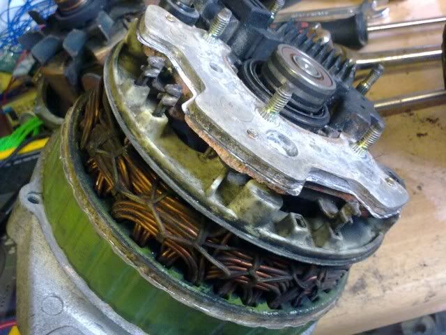
All three ends of the windings connect into the diode pack

Bottom view of diode pack
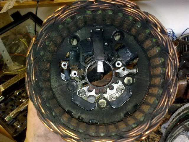
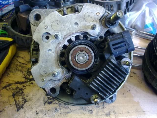
Top view of back end
As far as my (limited) understanding goes, as all the windings go into one connection that makes this a single phase alternator which produces AC at the windings which is rectified in the diode pack into DC which is output at the case (-tive) and the large bolt (+ive). The 2 pin connector I believe is for the dashboard ign light and tacho feed.
After stripping both the current and the old alternator I took some measurements:
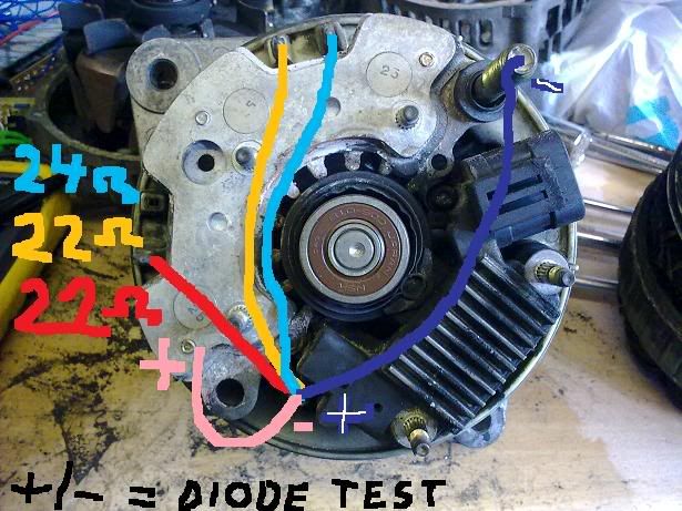
These were taken on the current not working alternator, impedence on the left and a diode check on the input and output of the diode pack. The resistance seems reasonable for a long run of copper wire, and the diode test seems to show the diode pack doing as it should. When I tried these same measurements on the old alternator I got .2 ohms on each wire, the diode test came out the same.
The question is (are!)
Do I understand correctly how these things work?
Am I taking the right readings?
If neither of these work (they don't) what readings should I get?
Steve
View of the positive end of the three sets of windings
All three ends of the windings connect into the diode pack
Bottom view of diode pack
Top view of back end
As far as my (limited) understanding goes, as all the windings go into one connection that makes this a single phase alternator which produces AC at the windings which is rectified in the diode pack into DC which is output at the case (-tive) and the large bolt (+ive). The 2 pin connector I believe is for the dashboard ign light and tacho feed.
After stripping both the current and the old alternator I took some measurements:
These were taken on the current not working alternator, impedence on the left and a diode check on the input and output of the diode pack. The resistance seems reasonable for a long run of copper wire, and the diode test seems to show the diode pack doing as it should. When I tried these same measurements on the old alternator I got .2 ohms on each wire, the diode test came out the same.
The question is (are!)
Do I understand correctly how these things work?
Am I taking the right readings?
If neither of these work (they don't) what readings should I get?
Steve