Fuse Box questions
Posted: Wed Sep 29, 2010 10:18 am
Hi all,
I've installed a rear-view/reversing camera and monitor, all working fine when powered from lighter socket. Now I want to wire it in 'permanently' to go on when the ignition is switched on.
I'm not an auto-electrician, but I'm reasonably handy with circuits, solder etc. I just can't read wiring diagrams for some reason!
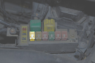
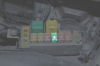
I think I've identified the switched power feed into the fuse box (top of F7, red/black chunky wire), but I'm a little puzzled about the internals of the fuse box.
The fuses only seem to have one wire 'attached' - does this mean that the incoming wire is going to a power 'bus' that feeds the other side of the fuses. If so, is there a piccy of the internal bus structure of the fuse box.
A quick poke seems to show that F1-F5 and F6-F8 are on seperate busses - the first being permanently on and the second switched. Is this correct?
If this is correct, can I just connect a fused wire to the bus-side of, say F8 (which is empty) - I would rather do this than splice into one of the other wires.
For my leisure battery, I took a big (fused) wire into a seperate fuse box and then took my feeds off the fuse box. I'd rather like to do this for the switched power too. I presume the big, incoming wire is fused ... but at what value - I'd like to use a smaller fuse for my feed from the bus.
Slightly seperately, I noticed that the switched power 'faded' when turned off (rather than just going to 0). Is this normal? It seemed to take a long time to drop, and I haven't seen it go below 0.8V - but I may not have waited long enough. Can this cause problems with equipment?
Thanks for your time
tim
I've installed a rear-view/reversing camera and monitor, all working fine when powered from lighter socket. Now I want to wire it in 'permanently' to go on when the ignition is switched on.
I'm not an auto-electrician, but I'm reasonably handy with circuits, solder etc. I just can't read wiring diagrams for some reason!
I think I've identified the switched power feed into the fuse box (top of F7, red/black chunky wire), but I'm a little puzzled about the internals of the fuse box.
The fuses only seem to have one wire 'attached' - does this mean that the incoming wire is going to a power 'bus' that feeds the other side of the fuses. If so, is there a piccy of the internal bus structure of the fuse box.
A quick poke seems to show that F1-F5 and F6-F8 are on seperate busses - the first being permanently on and the second switched. Is this correct?
If this is correct, can I just connect a fused wire to the bus-side of, say F8 (which is empty) - I would rather do this than splice into one of the other wires.
For my leisure battery, I took a big (fused) wire into a seperate fuse box and then took my feeds off the fuse box. I'd rather like to do this for the switched power too. I presume the big, incoming wire is fused ... but at what value - I'd like to use a smaller fuse for my feed from the bus.
Slightly seperately, I noticed that the switched power 'faded' when turned off (rather than just going to 0). Is this normal? It seemed to take a long time to drop, and I haven't seen it go below 0.8V - but I may not have waited long enough. Can this cause problems with equipment?
Thanks for your time
tim