


coolant flow - (follow up to cooling diagram)
Moderators: Doone, westonwarrior
-
Northern Bongolow

- Supreme Being
- Posts: 7724
- Joined: Mon Mar 15, 2010 11:33 pm
- Location: AKA Vanessa
Re: coolant flow - (follow up to cooling diagram)
looks bang on to me mate 

-
dandywarhol

- Supreme Being
- Posts: 5446
- Joined: Mon Dec 19, 2005 10:18 pm
- Location: Edinburgh
Re: coolant flow - (follow up to cooling diagram)
Beautiful animation I think the fully open position animation could have a "hotter" colour from the bottom of the radiator to the 'stat - but I suppose that all the "return" colours should be "hotter" too 
I think this exhaustive thread (and I have to admit to being adrift from it for a while, got a bit of boring time on my hands single finger typing post a left arm tendonitis operation ) really helps to explain the complex system extremely well and the hard work has to be applauded .
Also please bear in mind that convection currents play a large part of the heat transfer, not just the waterpump.
I think this exhaustive thread (and I have to admit to being adrift from it for a while, got a bit of boring time on my hands single finger typing post a left arm tendonitis operation
Also please bear in mind that convection currents play a large part of the heat transfer, not just the waterpump.
Whale oil beef hooked
Renault Lunar Telstar
Yamaha TD1C 250, Merc SLK200, KTM Duke 690
Renault Lunar Telstar
Yamaha TD1C 250, Merc SLK200, KTM Duke 690
-
widdowson2008

- Supreme Being
- Posts: 1703
- Joined: Tue Nov 18, 2008 10:15 pm
- Location: N.E.Derbyshire
Re: coolant flow - (follow up to cooling diagram)
Thank you for the kind words Dandy. Gotta remember though, this is a team effort.
You mention convection? Need someone else more knowledgable in this area cos I aint got a clue how to work it out.
Re colours on diagrams - Thought it easier to just indicate flow/returns to keep it simple.
Just realised, this all started exactly 1 year ago as yesterday with a simple question on this thread:
http://www.igmaynard.co.uk/bongo/forum/ ... =3&t=35902
Steve
-
dandywarhol
- Supreme Being
- Posts: 5446
- Joined: Mon Dec 19, 2005 10:18 pm
- Location: Edinburgh
Re: coolant flow - (follow up to cooling diagram)
Straight forward convection currents Steve - heat rises and all that........................
Earlier cars with high radiators didn't have waterpumps - the engine block was lower than the radiator bottom tank - they relied purely on convection thermal transfer to lift the hot coolant to the top of the radiator and then the cooler water gravity fed back into the engine block. In fact, modern systems are commonly known as pump ASSISTED cooling systems.

Earlier cars with high radiators didn't have waterpumps - the engine block was lower than the radiator bottom tank - they relied purely on convection thermal transfer to lift the hot coolant to the top of the radiator and then the cooler water gravity fed back into the engine block. In fact, modern systems are commonly known as pump ASSISTED cooling systems.
Whale oil beef hooked
Renault Lunar Telstar
Yamaha TD1C 250, Merc SLK200, KTM Duke 690
Renault Lunar Telstar
Yamaha TD1C 250, Merc SLK200, KTM Duke 690
-
The Great Pretender

- Supreme Being
- Posts: 2671
- Joined: Thu Oct 19, 2006 10:10 pm
- Location: Wigan
Re: coolant flow - (follow up to cooling diagram)
Not strictly true but understand what you mean, cooler water (coolant) is heavier and displaces the lighter hot medium, worked well with 10HP to contend with but and a BIG but it also allowed a clear path for any air to leave the engine. Modern design is all about reducing drag putting the rad below the outlet of the engines cooling system creating similar problems to ours, the possibility of trapped air.dandywarhol wrote:Straight forward convection currents Steve - heat rises and all that........................
To infinity and beyond
-
dandywarhol
- Supreme Being
- Posts: 5446
- Joined: Mon Dec 19, 2005 10:18 pm
- Location: Edinburgh
Re: coolant flow - (follow up to cooling diagram)
Succinctly put TGP and 100% correctThe Great Pretender wrote:Not strictly true but understand what you mean, cooler water (coolant) is heavier and displaces the lighter hot medium, worked well with 10HP to contend with but and a BIG but it also allowed a clear path for any air to leave the engine. Modern design is all about reducing drag putting the rad below the outlet of the engines cooling system creating similar problems to ours, the possibility of trapped air.dandywarhol wrote:Straight forward convection currents Steve - heat rises and all that........................

Jeebus, we'll be inviting each other around to dinner parties next......................................
Whale oil beef hooked
Renault Lunar Telstar
Yamaha TD1C 250, Merc SLK200, KTM Duke 690
Renault Lunar Telstar
Yamaha TD1C 250, Merc SLK200, KTM Duke 690
-
widdowson2008
- Supreme Being
- Posts: 1703
- Joined: Tue Nov 18, 2008 10:15 pm
- Location: N.E.Derbyshire
Re: coolant flow - (follow up to cooling diagram)
After poking around with a wire to try and see which direction the holes led, I decided to put this on record (before I destroy the head).
It shows all the cavities leading from the block and the 2 exits from the block.
The holes not coloured are for the holding down bolts and therefore of no interest in this excercise.
Now have a bit better idea of where to cut to expose the info I'm looking for. (I think )
Thanks for info dandy and tgp

It shows all the cavities leading from the block and the 2 exits from the block.
The holes not coloured are for the holding down bolts and therefore of no interest in this excercise.
Now have a bit better idea of where to cut to expose the info I'm looking for. (I think
Thanks for info dandy and tgp
Steve
-
phedders
- Bongolier
- Posts: 167
- Joined: Mon Jun 20, 2005 8:22 am
- Location: Coulsdon (Surrey/London)
- Contact:
Re: coolant flow - (follow up to cooling diagram)
Cant wait to see this bad boy cut up!
Location says where I am... I'd rather be justabout anywhere else! Suggestions or job offers of/in other parts of the UK gladly received...
-
widdowson2008
- Supreme Being
- Posts: 1703
- Joined: Tue Nov 18, 2008 10:15 pm
- Location: N.E.Derbyshire
Re: coolant flow - (follow up to cooling diagram)
Preliminary cutting pics. Hope Kirsty doesn't mind too much.  5 months ago, this head was on her Bongo.
Couldn't use the Plasma cutter - it was very busy with production work.
Finished up trying mechanical saw and this worked, even through hardened steel valve parts.
Will get more detailed pics of areas of particular interest when I have studied the bits. I have been able to establish all the coolant holes/paths and will post detailed info (together with pics) later.
The top of the radiator connection is at the same level as the inside of the head.
The top of the bypass connection is 15mm BELOW the inside of the head, and the bleed hose conection on the 'tree' is at the same level as the inside of the head.
I'll make some sense of the levels and come back.
Cutting

Cutting

Cutting

Assembled bits

Individual bits

Couldn't use the Plasma cutter - it was very busy with production work.
Finished up trying mechanical saw and this worked, even through hardened steel valve parts.
Will get more detailed pics of areas of particular interest when I have studied the bits. I have been able to establish all the coolant holes/paths and will post detailed info (together with pics) later.
The top of the radiator connection is at the same level as the inside of the head.
The top of the bypass connection is 15mm BELOW the inside of the head, and the bleed hose conection on the 'tree' is at the same level as the inside of the head.
I'll make some sense of the levels and come back.
Cutting
Cutting
Cutting
Assembled bits
Individual bits
Steve
-
Northern Bongolow
- Supreme Being
- Posts: 7724
- Joined: Mon Mar 15, 2010 11:33 pm
- Location: AKA Vanessa
Re: coolant flow - (follow up to cooling diagram)
superb steve!!! now we are getting somewhere!!
-
The Great Pretender
- Supreme Being
- Posts: 2671
- Joined: Thu Oct 19, 2006 10:10 pm
- Location: Wigan
Re: coolant flow - (follow up to cooling diagram)
Northern Bongolow wrote:superb steve!!!
To infinity and beyond
-
mikexgough

- Supreme Being
- Posts: 6158
- Joined: Mon Sep 08, 2008 9:02 pm
- Location: Cambridgeshire - where the all the Slodgers reside
- Contact:
Re: coolant flow - (follow up to cooling diagram)
I look forward to seeing if there are more answers here than I already know....
Conversant with Bongo Top Pinion Oil Seals
Bongo owning Velotech Cycle Mechanic
Bongo owning Velotech Cycle Mechanic
Re: coolant flow - (follow up to cooling diagram)
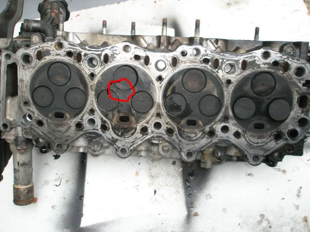
Hi widdowson2008,widdowson2008 wrote:You may think I know nowt about cylinder heads, and you would be correct. This is the very first one I have seen.
This cylinder head to be dissected was donated by a well respected member of the forum.
On initial viewing, there is a definite crack in the head at cylinder No.3 between inlet and exhaust port (as marked on pic.)
Also, I observed sooty deposits on the inlet port at the crack (also marked on pic), which suggests that exhaust gasses have been escaping into the inlet port.
Any light thrown on this would be gratefully received, ideally prior to cutting. Any more ideas where I should cut?
When I put the head to the knife (laser probably) I am hoping it may show the extent of the depth of this crack.

Did you find the extent of the crack.
-
widdowson2008
- Supreme Being
- Posts: 1703
- Joined: Tue Nov 18, 2008 10:15 pm
- Location: N.E.Derbyshire
Re: coolant flow - (follow up to cooling diagram)
It appears to be a surface crack - not deep at all. Having said that, it's deep enough to have let exhaust gasses into the inlet port. Quite scruffy in there compared to the other inlet ports.rita wrote: Hi widdowson2008,
Did you find the extent of the crack.
Not 100% sure (perhaps Allan could verify) but I think No.3 cylinder (where the crack is) had water in it, which would suggest that the crack extends into the waterways. Allan needs to confirm this. LORNA!!!!!!!!!!!!!!!!!!!
The one thing that is of possible interest here is that at the crack point, the thickness of the aluminium is only 6mm. Would that have a bearing on owt?
On the plus side, I have traced the many waterways and found out the path of all entry passages through to the exit ports. Will post diagram soon.
Info gathered using this pic
The head has a main chamber running the entire length of the head. All ports eventually lead into this chamber.
There are 2 exit ports (at the front end of the head), one going to the radiator and one to the thermostat bypass.
Using colours on attached pic:
BLUE PORTS - Lead directly to the main exit chamber.
RED PORTS - feed jackets around the inlet valve seats, then to the main exit chamber.
GREEN PORTS - go to feed jacket around the exhaust valves, then to the inlet valve seats, then to the main exit chamber.
YELLOW PORT - is directly from the oil cooler (I think) and straight into the main exit chamber
Diagram will explain it easier
Steve
-
maxheadroom

- Supreme Being
- Posts: 1950
- Joined: Wed Feb 28, 2007 6:37 pm
- Location: Gloucester
Re: coolant flow - (follow up to cooling diagram)
Mine had water in no. 2 cylinder from the crack see pictures.
crack
white crud from where water had boiled the last time it ran

crack
white crud from where water had boiled the last time it ran
Keep the Faith
